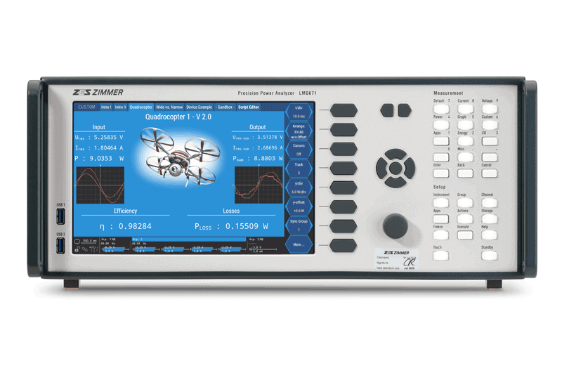
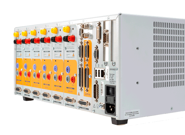
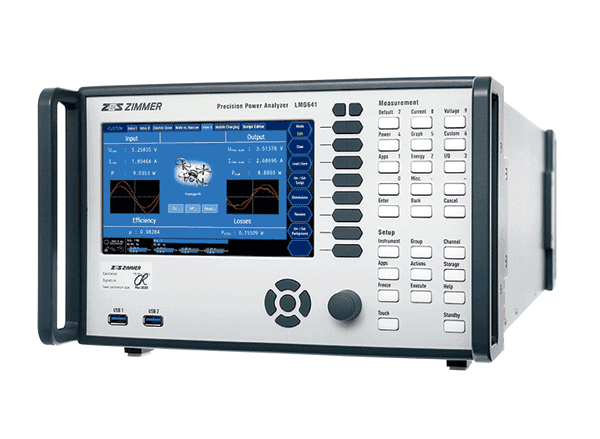
Målekanaler til ZES ZIMMER Power Analyzer LMG 600 serien.
For at give et bedre overblik over de forskellige målekanaler kommer her en lille oversigt. Målekanalerne kan sammensættes efter behov i jeres måleopgave. De bliver installeret ved ZES ZIMMER og kalibreret sammen med basen (LMG 641/671) for at give jer den bedst mulige nøjagtighed i jeres målinger.
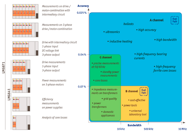
Målekanal C DC-10 kHz Båndbredde
Bruges f.eks. til præcisionsmålinger indenfor:
– 50/60 Hz – Standby Power – Power Transformer – Impedans på transformere – Core Losses – Forsyningskvalitet osv.
Nøjagtighed for U op til ±0,02% + 0,02% ved 45…65 Hz
Målekanal B DC-500 kHz Båndbredde
Bruges f.eks. til præcisionsmålinger indenfor:
– Cost-Effective – Power Tools – universelle laboratorie målinger – Power Transformer – Impedans på transformere – Forsyningskvalitet osv.
Nøjagtighed for U op til ±0,03% + 0,03% ved 45…65 Hz
Målekanal A DC-10 MHz Båndbredde
Bruges f.eks. til præcisionsmålinger indenfor:
– Inductive Heating – Ultrasonics – HF Ferrite Core Losses – høj nøjagtighed og båndbredde + samme områder som B og C målekanalen.
Kort sagt : ZES ZIMMERs målekanal med højeste bredbåndspræcision til de meget krævende opgaver.
Nøjagtigheder (A kanal):
±0,015% + 0,03% ved 0,05 Hz … 45 Hz + 65 Hz … 3 kHz
±0,01% + 0,02% ved 45…65 Hz
±0,03% + 0,06% ved 3…10 kHz
±0,2% + 0,4% ved 10…100 kHz
±0,5% + 1,0% ved 100 kHz … 1 MHz
For området : 1 MHz … 10 MHz benyttes følgende formel for at beregne nøjagtigheden:
± f/1 MHz*1.5 + f/1 MHz*1.5
Målekanal S
DC-10 MHz
Som A kanalen, men specielt udviklet til DC målinger op til 1.500 V CAT II, med måleområder specielt udvalgt til DC Læs mere om S kanalen her
Nøjagtighed : ± (% af målt værdi + % af max. peak værdi)
Max. målespænding
3200 VAC peak-peak // 1000 VAC TRMS
Overload beskyttelse
1000 V + 10 % kontinuert, 1500 V i 1 s, 2500 V i 20 ms
Input impedance (U)
2.69 MΩ, 4 pF
Earth Capacitance (U og I)
< 90 pF
Max. målestrøm
32 A TRMS
Max. peak
120 A
Overload Protection (short-time)
150 A i 10 ms
Alle målekanaler er galvanisk isolerede fra hinanden, anden intern elektronik og mod jord.
CAT III resp. 600 V / CAT IV
Her en oversigt over hvor og hvad de forskellige typer kanaler kan bruges:
Narrow- og Wideband RMS værdier og harmoniske i en enkelt måling – simultant og fri for Aliasing
Læs mere om DualPath nedenfor…
Sampling Rate
op til 1,2 Ms/s
Opløsning
Beregninger af RMS værdier med en min. Cycle af 10 ms
Nøjagtighed
Meget høj målenøjagtighed på 0,015% af den målte værdi + 0,01 % af måleområde limit
Dynamiske område
Fuld dynamisk område, kontinuert fra 500 µA til 32 A og 3 mV til 1000 V ; Powermåling mulig fra 0 – 100% load uden mekaniske ændringer
Båndbredde
Analog frekvensområde fra DC (0) – 10 MHz ; Analyse af 1000 harmoniske i GUI og 2000 via interface
Kontinuitet
Gapless Sampling ved 18 bit A/D converter opløsning og Cycle Time på 10 ms ; Ingen afbrydelser i målinger og komplet optagelse af alle relevante events
U-I Synkronicitet
Tids-offset mellem I og U input er justerbart ned til < 3 ns ; Meget nøjagtig måling af små Power Factors (PF) (under 0,01) og/eller høje frekvenser
Immunitet
Pålidelig i områder med udfordrende elektromagnetiske konditioner
Ground Capacitance
Lav jordkapacitance på under 90 pF
DualPath
In conventional power analyzers, a signal first undergoes analog conditioning. Then the output is optionally fed through an antialiasing filter (AAF) before it gets digitized by an A/D converter and awaits further processing. The decision for or against the AAF has to be taken before sampling, as this is when aliasing occurs. It cannot be undone later on. RMS values can be determined without risk of aliasing due to their statistical nature, all other measurements need to be handled with care. Due to the limitation to a single A/D converter, there are inherently some downsides to be factored in with conventional devices.
If the goal is to measure RMS power both over the entire bandwidth and at the fundamental frequency, unfiltered and filtered measurements could be alternated – in theory. In practice, it is of utmost difficulty to exactly reproduce the same operating point twice. Unless this can be guaranteed, all comparisons between results are void due to lack of repeatability. Besides, this procedure is extremely time-consuming. If one variant is skipped in order to save time, the results are inevitably error-prone. If the filter remains activated to avoid aliasing with the FFT, bandwidth gets sacrificed when measuring RMS values. Switching off the AAF voids the FFT. If it is carried out nevertheless, the quality of the results is questionable. An aliasing error of 50%, for instance, is easily detected, however a deviation of 0.5% could go unnoticed.
In the end, all of the aforementioned measurement methods are merely unsatisfactory compromises. This is why ZES ZIMMER has fundamentally redesigned signal processing and developed the DualPath architecture. The analog side is the same as in conventional measuring devices, however the subsequent digital processing has been revolutionized. Only power analyzers of the LMG600 series are equipped with two A/D converters in two independent signal paths for each current and voltage channel. One, for the filterless measurement of the wideband signal, and another, for the narrowband signal at the output of the antialiasing filter.
The parallel processing of the digitized sample values gives the user access to both measurements of the same signal, without risking aliasing effects. This unique procedure avoids all of the downsides of previous approaches and guarantees the most precise result in the shortest time possible.
The instruments of manufacturer Y are sampling with all filters removed, and allow you to apply digital filtering later on in order to isolate narrowband values – does this not achieve the same results as DualPath? No, it merely proves the Nyquist-Shannon theorem and the subject of aliasing have not been properly grasped. Frequency portions for whom the sampling rate is insufficient according to the theorem need to be removed prior to filtering, as they can no longer be identified after sampling. E.g. a signal at 50 Hz below the sampling rate would show up at 50 Hz after sampling. This signal, which has been created by undersampling, is indistinguishable from the original signal, since part of the original information has been wiped out due to the insufficient sampling rate.
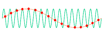
ZES ZIMMER DualPath Frequency exampleThe green line represents a high-frequency (2 MHz) signal before sampling, the red dots show the result of undersampling – here with a rate slightly higher than the signal frequency (2.125 MHz). The erroneous sampling process, since too slow according to the Nyquist-Shannon theorem, creates a “phantom signal” at a frequency of (2.125 MHz – 2 MHz = 125 kHz), which is merely 1/16 of the original frequency and can no longer be distinguished from the genuine signal content around 125 kHz.
In that range, e.g. harmonics of a frequency converter’s switching frequency might appear, which would in turn be distorted by the “phantom signal”. The knowledge that part of the power measured around 125 kHz stems from the undersampled 2 MHz signal is irretrievably lost. The above values are merely examples, the erroneous frequency components might as well appear near the fundamental of the unit under test. Trying to identify these components after the fact and to remove them would be as futile as striving to identify blue objects on a color photography reduced to black and white – the information “color“ is irretrievably lost, the remaining information “brightness“ is by no means equivalent.
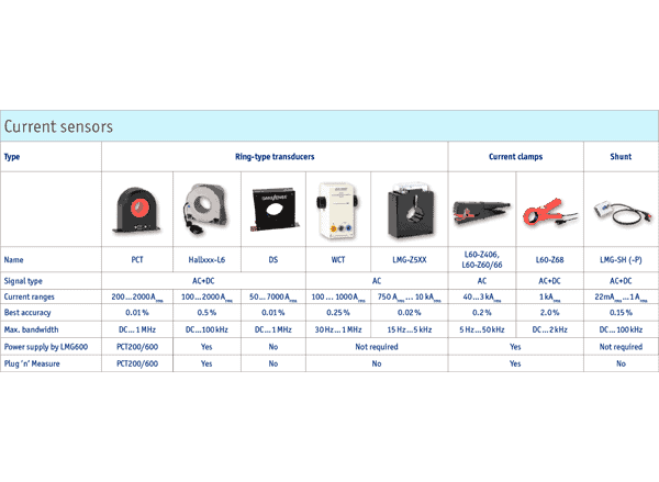
ZES ZIMMER Current Sensors, Clamps and Transformers