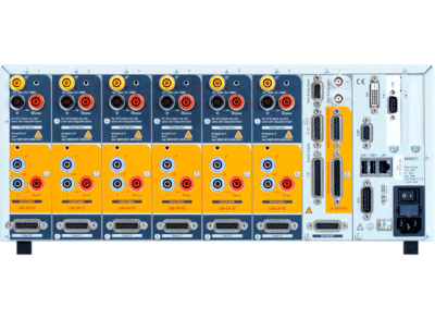
Modulbaseret teknologi gør det nemt at konfigurere den til netop din opgave.
Frit konfigurerbar med 1 til 4 målekanaler med høj præcision fra 500 µA op til 32 A.
Gruppér kanalerne efter behov og sync til forskellige frekvenser for hver kanalgruppe.
I/O modul for samtidig måling/registrering af elektriske- og mekaniske data. Se mere under Features.
Harmonisk & interharmonisk analyse op til 400th & 2000th.
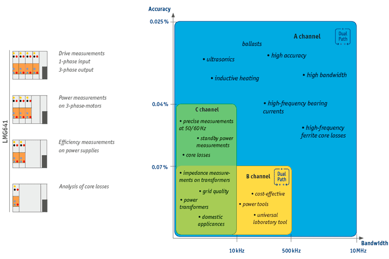
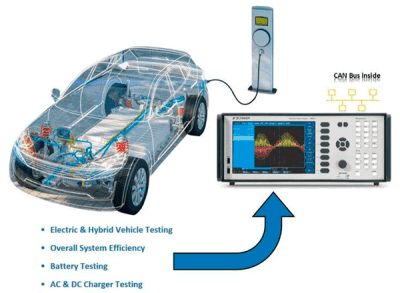
Præcisions powermåling på elektromotorer, transformere, frekvensomformere, halvledere, belysningselektronik, power supply, power electronics m.v.
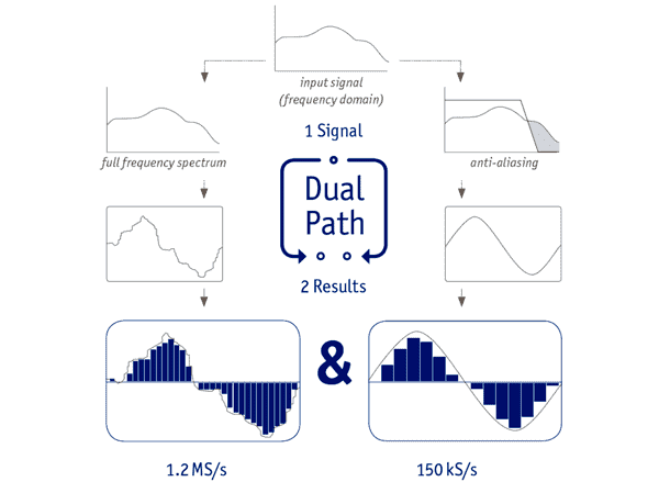
ZES ZIMMERs unikke DualPath design for måling i power elektronik med højfrekvent indhold, for samtidig display af hele power spektrum og specifikt udvalgt spektrum. Dermed får man 2 analyser af samme signal uden delay og aliasing problemer.
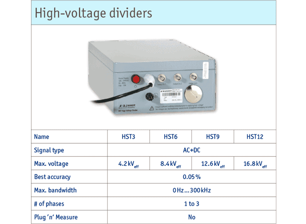
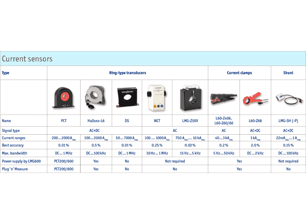
Stort udvalg i strøm-sensorer, -tænger og -trafoer. Genkendes automatisk af LMG641 og setup af målekanalen sker også automatisk – ”Plug and Measure”.
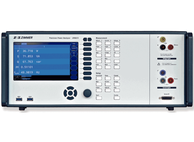
Den store 7” skærm kan, i en dedikeret ”Custom Menu”, konfigureres så det passer jeres opgave og der bliver vist netop de data og grafer der er brug for.
Registrering af alle data og målinger sker til den indbyggede SSD. Her taler vi om op til 1.2 MS pr. kanal i 18bit + analog I/O målinger. Det hele i Real-Time.
Integrérbar i CAN bus : Bi-Directional CAN interface for fjernstyring via CAN.
LMG641 vs. LMG671
* Mindre instrumenthus
* Undtagelse i ARON kobling ved måling af effekt er begrænset
* Til måling af trefaset effekt med kun to power kanaler.
* LMG641 kan beregne den manglende kanals variable.
Nyt i firmware version 3.021
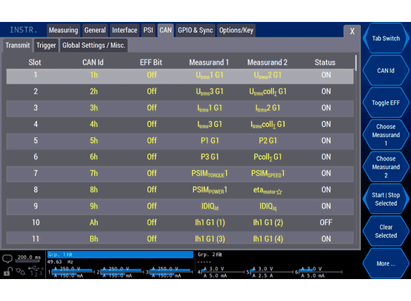
CAN bus som kommunikationssystem spiller en dominerende rolle i bl.a. automobilbranchen og vil fortsat være en afgørende faktor i fremtiden. Med stadigt voksende udvikling og innovation indenfor elektriske drev, stiger kravende til både dybdeanalyse og levering af data fra Power Analyzeren via CAN bus.
ZES ZIMMERs LMG600 serie, var den første Power Analyzer med Bi-Directional CAN Interface med op til 128 målte værdier på bussen. Fra og med “firmware version 3.021”, nu op til 256 – dvs. dobbelt så mange målte værdier kan nu blive sendt. Brugeren konfigurerer en CAN besked med op til 2 målte værdier så belastningen af CAN bussen ikke øges men effektiviteten af datatransmissionen øges. Dette er især en hjælp ved Multi-phase applikationer og ved transmission af mange udlæsninger, såsom: broadband current, voltage, power values, individual harmonics – men også motorrelevante udlæsninger, som: speed, torque, d-axis og q-axis components osv.
Den seneste Firmware er tilgængelig på forespørgsel.
In conventional power analyzers, a signal first undergoes analog conditioning. Then the output is optionally fed through an antialiasing filter (AAF) before it gets digitized by an A/D converter and awaits further processing. The decision for or against the AAF has to be taken before sampling, as this is when aliasing occurs. It cannot be undone later on. RMS values can be determined without risk of aliasing due to their statistical nature, all other measurements need to be handled with care.
Due to the limitation to a single A/D converter, there are inherently some downsides to be factored in with conventional devices. If the goal is to measure RMS power both over the entire bandwidth and at the fundamental frequency, unfiltered and filtered measurements could be alternated – in theory. In practice, it is of utmost difficulty to exactly reproduce the same operating point twice. Unless this can be guaranteed, all comparisons between results are void due to lack of repeatability. Besides, this procedure is extremely time-consuming.
If one variant is skipped in order to save time, the results are inevitably error-prone. If the filter remains activated to avoid aliasing with the FFT, bandwidth gets sacrificed when measuring RMS values. Switching off the AAF voids the FFT. If it is carried out nevertheless, the quality of the results is questionable. An aliasing error of 50%, for instance, is easily detected, however a deviation of 0.5% could go unnoticed.
In the end, all of the aforementioned measurement methods are merely unsatisfactory compromises. This is why ZES ZIMMER has fundamentally redesigned signal processing and developed the DualPath architecture. The analog side is the same as in conventional measuring devices, however the subsequent digital processing has been revolutionized. Only power analyzers of the LMG600 series are equipped with two A/D converters in two independent signal paths for each current and voltage channel. One, for the filterless measurement of the wideband signal, and another, for the narrowband signal at the output of the antialiasing filter.
The parallel processing of the digitized sample values gives the user access to both measurements of the same signal, without risking aliasing effects. This unique procedure avoids all of the downsides of previous approaches and guarantees the most precise result in the shortest time possible.
The instruments of manufacturer Y are sampling with all filters removed, and allow you to apply digital filtering later on in order to isolate narrowband values – does this not achieve the same results as DualPath? No, it merely proves the Nyquist-Shannon theorem and the subject of aliasing have not been properly grasped. Frequency portions for whom the sampling rate is insufficient according to the theorem need to be removed prior to filtering, as they can no longer be identified after sampling. E.g. a signal at 50 Hz below the sampling rate would show up at 50 Hz after sampling. This signal, which has been created by undersampling, is indistinguishable from the original signal, since part of the original information has been wiped out due to the insufficient sampling rate.
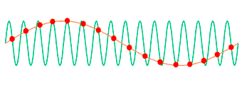
ZES ZIMMER DualPath Frequency example:
The green line represents a high-frequency (2 MHz) signal before sampling, the red dots show the result of undersampling – here with a rate slightly higher than the signal frequency (2.125 MHz). The erroneous sampling process, since too slow according to the Nyquist-Shannon theorem, creates a “phantom signal” at a frequency of (2.125 MHz – 2 MHz = 125 kHz), which is merely 1/16 of the original frequency and can no longer be distinguished from the genuine signal content around 125 kHz. In that range, e.g. harmonics of a frequency converter’s switching frequency might appear, which would in turn be distorted by the “phantom signal”.
The knowledge that part of the power measured around 125 kHz stems from the undersampled 2 MHz signal is irretrievably lost. The above values are merely examples, the erroneous frequency components might as well appear near the fundamental of the unit under test. Trying to identify these components after the fact and to remove them would be as futile as striving to identify blue objects on a color photography reduced to black and white – the information “color“ is irretrievably lost, the remaining information “brightness“ is by no means equivalent.
PSI – Process Signal Interface
It is often necessary to take further measurements in addition to electrical parameters to be able to make a meaningful overall statement on the performance and efficiency of the device being tested. Hence, it is vital to be able to perfectly synchronize these measured values with the RMS values calculated by the LMG600, in order to establish reliable timing between electrical and mechanical events. A typical application is the analysis of electrical drive systems, where torque and speed must be measured and reconciled with the electrical parameters. Conversely, it may also be necessary for the power analyzer to output results as analog signals for further processing, or to trigger switching operations depending on measured variables or derived values. In order to be equipped for all of these potential requirements, the LMG600 offers a multitude of different input/output features for analog and digital signals.
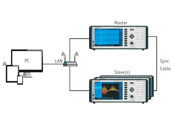
The LMG600 series already offers the highest channel count per chassis in the power analyzer market, yet there are applications which require 8 or more points of power measurement. The solution is simple: combine multiple LMG600 chassis’ to create a virtual power analyzer with more channels. All you need to do is to connect the individual units via sync cable, and they will automatically synchronize:
* Cycle Timing
* System Time
* Transient Triggere Events
*State of Energy Integration
ZES ZIMMER Master-Slave Setup:
Power analysatorer findes med forskellig målenøjagtighed, så brugeren kan vælge den rigtige opsætning/løsning til opgaven. Det er ikke alle opgaver der kræver den højeste målenøjagtighed, men ofte er en lavere oplysning og båndbredde tilstrækkelig. Det er heller ikke altid så simpelt og nogle opgaver kræver måske forskellig båndbredde og nøjagtigheder.
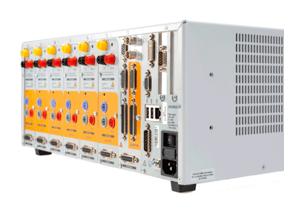
Derfor byder LMG600 serien på 3 forskellige målekanaler, som kan kombineres efter ønske og opgave i samme kabinet.
ZES ZIMMER LMG641 Measurement Channels
Se mere her omkring den nye S-Kanal (DC målekanal)
System:
* 1 til 4 målekanaler for spænding og strøm (max 3 kanaler + I/O modul) (Galvanisk adskilte)
* Gapless sampling op til 18 bit og cycle time <30 ms.
* Med option: I/O kort speed/drejningsmoment indgang, frit konfigurerbar for alle signaler (analog, frekvens som RS422, TTL eller HTL)
* Flikker måling, interaktion mellem grid og appliance iht. EN61000-4-15.
* Signalfilter fri konfigurerbar frekvens, type og karakteristik. Synkronisering af op til 7 forskellige frekvenser samtidig.
* Scope funktion: Grafisk display af sample værdier over tid.
* Plot funktion: To time (trend) diagram af max. 8 parametre, max. opløsning 30 ms.
* Delay Time mellem V og I indgang <3 ns, meget præcise målinger ved lille power faktor (PF) og/eller høje frekvenser.
* Samtidig måling af V, I, P og harmoniske – vist numerisk i tabelform eller som grafiske kurver.
* Samtidig måling af narrow- og broadband værdier, med DualPath setup.
* Samtidig måling af fundamental frekvens og broadband RMS værdier for øjeblik detektering af tab, henholdsvis højfrekvens del.
* Harmonisk og interharmonisk op til 400th og 2000th, iht. EN61000-4-7. af U, I, P, Q og S
* Hukommelse og interface: Intern hukommelse + SSD for langtidsmålinger. USB2.0, Gbit-LAN, RS-232 og DVI / VGA.
* Touchskærm. 7″ VGA
* Dimensioner bench udførelse 284 x 177 x 590 mm.
* Vægt max. 14 kg med 4 målekanaler installeret. Rack 4 HE.
* Omgivelses temperatur for drift: 5 til 40°C
* Driftsspænding: 100 til 230 V, 47 til 63 Hz, max. 400 W.
* LMG-Control PC software Basis modul for konfigurering og betjening af LMG641 via PC
* 2 års garanti.
* Leveres med kalibreringscertifikat.
Optioner:
Ekstern grafisk interface (L671-OPT-DVI): DVI interface for ekstern skærm.
Proces Signal Interface (L6-OPT-PSI):
* 2 fast analog inputs (150 kS/s, 16 bit BNC)
* 8 analog inputs (100 S/s, 16 bit)
* 32 analog outputs 14 bit
* 8 switching outputs
* 8 switching inputs 150 kS/s
* Speed-/torque-/frekvens inputs 150 kS/s.
Stjerne-trekant konvertering (L6-OPT-SDC): Konvertering af netspænding til fasespænding, for beregning af power.
Harmoniske (L6-OPT-HRM): Harmoniske og interharmoniske, max 2000th orden, af U, I, P, Q og S
CE Harmoniske (L6-OPT-HRM) : Acc. to IEC 61000-4-7
Flikker (L6-OPT-FLK): Acc. IEC 61000-4-15
LMG Test Suite: Complete Test Package for Conformity Tests acc. to:
* IEC EN 61000-3-2 & 61000-3-12 for harmonics (LMG-TEST-CE-HRM)
* IEC EN 61000-3-3 & 61000-3-11 for flicker (LMG-TEST-CE-FLK)
* IEC 62301 & EN 50564 for standby power (LMG-TEST-CE-STBY)
Tilbehør:
ZES ZIMMERs store >200 siders sensor katalog, tilsendes gerne på e-mail.
Den seneste Firmware er tilgængelig på forespørgsel.
ChangeLog fil kan sendes på forespørgsel.
Nyeste Softwareversion : Firmware version 3.123
Tidligere versioner:
New features:
– Test Suite: New pre-test to evaluate THC for IEC 61000-3-2 [RM#4359]
– LMG-Control: Multiple Versions can be installed in parallel [RM#5056]
New features:
– Test Suite: Add support for split-phase (Single-Phase 3-Wire) systems in standby tests [RM#4953]
– Script Editor: Possibility to start energy measurement on individual groups [RM#4305]
New features:
– Initial support for S2 power channels [RM#3008]
– Direct download of manual in help system [RM#4036]
– Test Suite: Improvement of the formatting of raw values in test report [RM#4095]
– Test Suite: Add support for RI 2415 [RM#2956]
– Test Suite: Added preview of IEC 61000-3-16 (1108/CD) [RM#2552]
– Test Suite: Allow saving to network drives [RM#3040]
– LMG-Control: Windows-Installer is now signed [RM#2395]
– SampleVision: add linear-y scaling option to spectrum [RM#2475]
Firmware version 3.051
New features:
– GUI: Validation of sufficient CAN-bus transmit bandwidth by softkey. [RM#2423]
– Test Suite: Add sampling-interval to the report for standby measurements. [RM#2300]
– Sample Vision: Prevent accidental gaps in recording. [RM#2332]
CAN bus som kommunikationssystem spiller en dominerende rolle i bl.a. automobilbranchen og vil fortsat være en afgørende faktor i fremtiden. Med stadigt voksende udvikling og innovation indenfor elektriske drev, stiger kravende til både dybdeanalyse og levering af data fra Power Analyzeren via CAN bus.
ZES ZIMMERs LMG600 serie, var den første Power Analyzer med Bi-Directional CAN Interface med op til 128 målte værdier på bussen. Fra og med “firmware version 3.021”, nu op til 256 – dvs. dobbelt så mange målte værdier kan nu blive sendt. Brugeren konfigurerer en CAN besked med op til 2 målte værdier så belastningen af CAN bussen ikke øges men effektiviteten af datatransmissionen øges. Dette er især en hjælp ved Multi-phase applikationer og ved transmission af mange udlæsninger, såsom: broadband current, voltage, power values, individual harmonics – men også motorrelevante udlæsninger, som: speed, torque, d-axis og q-axis components osv.